RISK: the likelihood that an event will occur and result in damages.
HAZARD: something with the potential to cause harm and damages.
To be safe, we must reduce both the RISK (frequency) and the HAZARD (magnitude), the American National Standards Institute has developed a structured approach using a Hierarchy of Hazard Control Measures.
The first choice is to “eliminate the hazard during design.” This is the most effective control measure and must always be considered first. If the hazard cannot be eliminated completely, then there are a number of control options that can be used to prevent or minimize exposure to the risk:
IEEE 242-1986 7.2.5
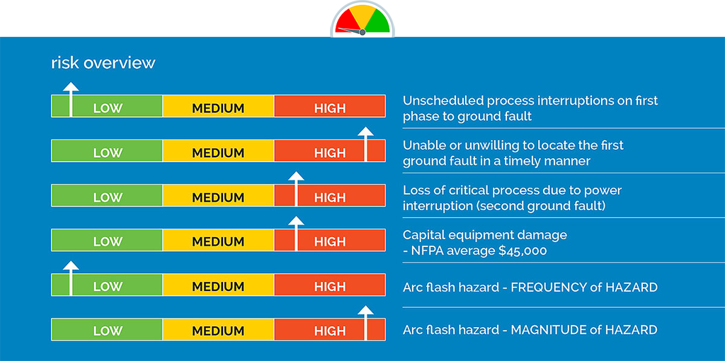
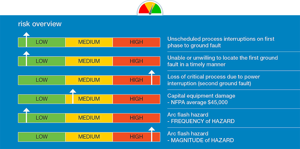
Ungrounded systems offer no advantage over high-resistance grounded systems in terms of continuity of service and have the disadvantages of transient over-voltages, locating the first fault and burn downs from a second ground fault.
FM Global 5-18 Protection of Electrical Equipment Single Phase and Other Related Faults
FM Global 5-10 Protective Grounding for Electric Power Systems and Equipment

During a ground of sufficient magnitude the process is interrupted resulting in unscheduled downtime. If the ground fault current is insufficient, then an arcing ground fault will occur.
IEEE Std 242-2001 (Buff Book)
8.2.2. One disadvantage of the solidly grounded system involves the high magnitude of destructive, arcing ground-fault currents that can occur.
IEEE Std 141-1993 (Red Book)
7.2.4. The solidly grounded system has the high probability of escalating into a phase-to-phase or three-phase arcing fault, particularly for the 480V and 600V systems.
IEEE Std 141-1993 (Red Book)
7.2.2. High-resistance grounding provides the same advantages as ungrounded systems yet limits the steady state and severe transient over-voltages associated with ungrounded systems. There is no arc flash hazard [for LV ground faults], as there is with a solidly grounded system, since the fault current is limited to approximately 5A.
IEEE Std 242-1986 Recommended Practice for the Protection and Coordination of Industrial and Commercial Power Systems
• 7.2.5. Ungrounded systems offer no advantage over high-resistance grounded systems in terms of continuity of service and have the disadvantages of transient overvoltage's, locating the first fault and burn downs from a second ground fault. For these reasons, they are being used less frequently today than high-resistance grounded systems.

Advanced or SMART HRG systems allow for identifying and isolating a selected feeder on the occurrence of a second ground fault ensuring critical processes remain operational.

A great majority of electrical faults are of the phase-to-ground type. High-resistance grounding will insert an impedance in the ground return path and below (at 5 kV nominal or below), leaving insufficient fault energy and thereby helping reduce the arc flash hazard level.
An arc flash relay typically uses light sensors to detect the light produced by an arc flash event. Once a certain level of light is detected the relay will issue a trip signal to an upstream overcurrent device.
NFPA 70E and CSA Z 462 Annex 0 General Design Requirements 0.2.2: Design option decision should facilitate the ability to eliminate hazards or reduce risk by doing the following: